
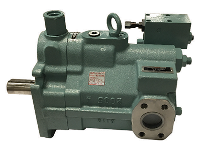
PZS-3A-70N3Q1-E10
Description: Variable Volume Piston Pump
High Pressure, High Reliability
The PZS Variable Volume Piston Pump offers the perfect combination of high pressure and high reliability with energy efficient capabilities that maintain the discharge rate at a desired level.
Low Noise, Low Vibration Operation
The semi-cylindrical swash plate provides high support and rigidity which makes it possible to increase the number of pistons (from 9 to 11) and equip optimal valve plates all of which makes low noise possible.
High Reliability, Long Life
O-ring seals, used for mating surfaces, eliminate oil leaks. A spherical valve plate renders a stable operation by maintaining optimal hydraulic pressure balance across a wide range and contamination resistance characteristics.
The PZS Variable Volume Piston Pump can be used as a stand alone or combined with an IP pump with an adapter kit for a wide ranging number of applications.
Features:
| Spec | Value |
|---|---|
| Series | PZS |
| Pump Size | 3 |
| Mounting Method | A: Foot Type |
| Pump Capacity | 70 (cm³/rev) |
| Variable Control Mechanism | NQ: 2-Pressure; 2-Flow Rate Control |
| Pressure Adjustment Range | 3: 291-3000 psi |
| High Pressure Range | 1: 291-1000 |
| Design Number | E10 |
| Weight (lb/kg) | 111.4 / 50.5 |
Values provided may differ based on other specifications. Please consult the product documentation for values specific to the model number.
*Please consult product documentation for specific values
Additional Documents:
Looking for distributors outside of the US? Find Mexican Distributors or Canadian Distributors
Notes:
- Pressure Compensation (N)
PZS-5B/6B maximum operating pressure: 3642 psi- 2-Pressure Control System (WS)
PZS-5B/6B maximum operating pressure: 3625 psi- 2-Pressure, 2 Flow-Rate Control Type (NQ)
PZS-5B maximum operating pressure: 3642 psi- Solenoid Cutoff Control Type (RS)
PZS-5B/6B maximum operating pressure: 3625 psi
Handling:
- Use flexible couplings for connecting the pump shaft to the drive shaft and to prevent radial or thrust load from being applied to the pump shaft.
- Eccentricity between the drive shaft and pump shaft should be no greater than 0.05mm with an eccentric angle error of 1 inch or less.
- Keep the fitting length of couplings and pump shafts at least 2/3 the length of the coupling width.
- Use a sufficiently rigid pump mounting base.
- Set pump suction side pressure to -4.35 lbs/in² (-0.03 MPa) or more (suction port flow velocity less than 2 m/sec).
- Raise part of the drain piping so it is above the top most part of the pump body and insert the return section of the drain piping into the hydraulic operating fluid. Also, observe the values in Table 1 in order to limit the drain back pressure to 14.5 lbs/in² (0.1 MPa).
- Mount the pump shaft so that it is oriented horizontally.
- The use of rubber hose is recommended in order to minimize noise and vibration.
- Check valve is located on the discharge side of the pump to prevent reverse rotation and damage to the pump when turned in the off position.
Similar Items (11)

Variable Volume Piston Pump
PZS-3A-70N1Q1-E10Variable Volume Piston Pump
PZS-3A-70N3Q3-E10Variable Volume Piston Pump
PZS-3A-70N4Q1-E10Variable Volume Piston Pump
PZS-3A-70N4Q3-E10Variable Volume Piston Pump
PZS-3A-70N4Q4-E10Variable Volume Piston Pump
PZS-3B-70N1Q1-E10Variable Volume Piston Pump
PZS-3B-70N3Q1-E10Variable Volume Piston Pump
PZS-3B-70N3Q3-E10Variable Volume Piston Pump
PZS-3B-70N4Q1-E10Variable Volume Piston Pump
PZS-3B-70N4Q3-E10Variable Volume Piston Pump
PZS-3B-70N4Q4-E10