
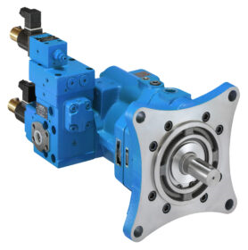
PZ-3A-70E3A-10
Description: Load Sensitive Variable Piston Pump
The PZ Load Sensitive Variable Piston Pump utilizes the semi-cylindrical swash plate that is part of the basic technology used by the PVS Series Variable Piston Pump. This pump adds a hydrostatic bearing mechanism, valve plate, and other noise reducing mechanisms for operation making it even quieter than the PVS. The pump body houses an electro-hydraulic proportional control valve, compensator, and surge cutoff valve that eliminates the need for superfluous piping. The electro-hydraulic proportional control valve uses the proven force feedback system for improved hysteresis, repeatability, and response. The ability to create a double pump configuration with an IP Pump further expands the range of possible applications.
Features:
| Spec | Value |
|---|---|
| Model | PZ |
| Pump Size | 3 |
| Mounting Method | A: Foot Type Mounting |
| Variable Pump Capacity | 70: (cu in/rev) |
| Control Mechanism | EA: Load Response Control |
| Pressure Adj Range | 3: 290 - 3000 psi |
| Design Number | 10: SAE Piping |
| Weight (lb/kg) | 202.9 / 92 |
Values provided may differ based on other specifications. Please consult the product documentation for values specific to the model number.
*Please consult product documentation for specific values
Additional Documents:
Looking for distributors outside of the US? Find Mexican Distributors or Canadian Distributors
Notes:
- Can be used in combination with an IP pump to configure a fixed discharge pump.
- The PZ-4B-130 model number has changed to PZ-5B-130.
- Maximum flow rate depends on the revolution speed.
Handling:
- Use flexible couplings for connecting the pump shaft to the drive shaft and to prevent radial or thrust load from being applied to the pump shaft.
- Eccentricity between the drive shaft and pump shaft should be no greater than 0.05mm with an eccentric angle error of 1 inch or less.
- Keep the fitting length of couplings and pump shafts at least 2/3 the length of the coupling width.
- Use a sufficiently rigid pump mounting base.
- Set pump suction side pressure to -4.35 lbs/in² (-0.03 MPa) or more (suction port flow velocity less than 2 m/sec).
- Raise part of the drain piping so it is above the top most part of the pump body and insert the return section of the drain piping into the hydraulic operating fluid. Observe the values in Table 1 in order to limit the drain back pressure to 14.5 lbs/in² (0.1 MPa).
- Mount the pump shaft so that it is oriented horizontally.
- The use of rubber hose is recommended in order to minimize noise and vibration.
- Check valve is located on the discharge side of the pump to prevent reverse rotation and damage to the pump when turned in the off position.
Similar Items (41)

Load Sensitive Variable Piston Pump
PZ-2A-35E1A-11Load Sensitive Variable Piston Pump
PZ-2A-35E2A-11Load Sensitive Variable Piston Pump
PZ-2A-35E3A-11Load Sensitive Variable Piston Pump
PZ-2B-35E1A-11Load Sensitive Variable Piston Pump
PZ-2B-35E2A-11Load Sensitive Variable Piston Pump
PZ-2B-35E3A-11Load Sensitive Variable Piston Pump
PZ-2A-45E1A-11Load Sensitive Variable Piston Pump
PZ-2A-45E2A-11Load Sensitive Variable Piston Pump
PZ-2A-45E3A-11Load Sensitive Variable Piston Pump
PZ-2B-45E1A-11Load Sensitive Variable Piston Pump
PZ-2B-45E2A-11Load Sensitive Variable Piston Pump
PZ-2B-45E3A-11Load Sensitive Variable Piston Pump
PZ-3A-70E1A-10Load Sensitive Variable Piston Pump
PZ-3A-70E2A-10Load Sensitive Variable Piston Pump
PZ-3B-70E1A-10Load Sensitive Variable Piston Pump
PZ-3B-70E2A-10Load Sensitive Variable Piston Pump
PZ-3B-70E3A-10Load Sensitive Variable Piston Pump
PZ-4A-100E1A-10