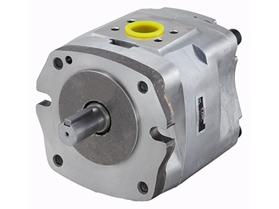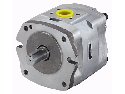
IPH-2B-8-EL-11
Description: IP Pump
The IPH Series IP Pump is a high-efficiency patented axial and radial pressure loading system that offers outstanding durability and very long life. A modified involute short-tooth gear enables internal gearing for reduced pulsation and exceptionally quiet operation. The simple structure makes maintenance and inspection easy.
Features:
| Spec | Value |
|---|---|
| Series | IPH |
| Size | 2 |
| Mount | B: Flange Type |
| Capacity | 8 (cm³/rev) |
| Auxiliary Symbol | E: Welded Type Flange Kit; L: Counterclockwise (Viewed From Shaft End) |
| Design | 11: For 2A; 2B; 5B; 6B |
| Weight (lb/kg) | 6.2 / 2.8 |
Values provided may differ based on other specifications. Please consult the product documentation for values specific to the model number.
*Please consult product documentation for specific values
Additional Documents:
Looking for distributors outside of the US? Find Mexican Distributors or Canadian Distributors
Notes:
- Capacity: Logical discharge rate per rotation.
- Suction Pressure: 2.9 to 44 psi (+0.02 to +0.3MPa) {-0.2 to + 0.3kgf/cm²}
- Maximum working pressure is the pressure limit when there are frequent pressure changes.
- Avoid installation with the suction port towards the bottom of the pump.
- Specify using the model number format when pipe flanges are required.
Handling:
- For the hydraulic operating fluid, use an R&O type and wear-resistant type of ISO VG32 to 68 or equivalent (viscosity index of at least 90). Use hydraulic operating fluid that provides kinematic viscosity during operation in the range of 20 to 150 mm²/s.
- The operating temperature range is 40 to 149°F. When the oil temperature at startup is 40°F or less, perform a warm-up operation at low pressure until the oil temperature reaches 40°F. Use the pump in an area where the tempera-ture is within the range of 32 to 140°F.
- Suction pressure is 2.9 to 44 psi, and the suction port flow rate should be to greater than 6 ft/sec.
- Avoid pulley, gear, and other drive systems that impart a radial or thrust load on the end of the pump shaft.
- Mount the hydraulic pump so its pump shaft is oriented horizontally. Provide a suction strainer with a filtering grade of about 100µm (150 mesh). For the return line to the tank, use a 25µm line filter.
- Manage hydraulic operating fluid so contamination is maintained at class NAS10 or lower. Take care to avoid contamination with water and other foreign matter, and watch for discoloration. Whitish fluid indicates that air has contaminated the fluid, and brownish fluid indicates the fluid is dirty.
- Operate within the minimum RPM range of the pump. Unload the pumps load pressure to operate at variable speeds. Condition of inflow piping must produce as little inflow load pressure as possible to minimize effect of cavitation.
- When using water or glycol based hydraulic operating fluid, refer to Water-Glycol Type Operation Fluid Hydraulic Devices section in the catalog (pg. N-3) for details on applicable models of hydraulic pumps.
- At startup, repeat the inching operation (start-stop) to bleed air from the pump and pipes.
- Equip an air bleed valve in circuits where it is difficult to bleed air before startup.
- To ensure proper lubrication of the pumps rubbing surfaces, supply oil to the interior of the pump before starting operation.
- When centering the pump shaft, eccentricity with the motor shaft should be no greater than 0.05 mm. Use a pump mounting base of sufficient rigidity. The angle error should be no greater than 1°.
Similar Items (17)

IP Pump
IPH-2B-8-11
IP Pump
IPH-2B-8-T-11
IP Pump
IPH-2B-8-E-11
IP Pump
IPH-2B-8-L-11
IP Pump
IPH-2B-8-LT-11
IP Pump
IPH-2A-8-11
IP Pump
IPH-2A-8-T-11
IP Pump
IPH-2A-8-E-11
IP Pump
IPH-2A-8-L-11
IP Pump
IPH-2A-8-LT-11
IP Pump
IPH-2A-8-EL-11
IP Pump
IPH-2H-8-11
IP Pump
IPH-2H-8-T-11
IP Pump
IPH-2H-8-E-11
IP Pump
IPH-2H-8-L-11
IP Pump
IPH-2H-8-LT-11
IP Pump
IPH-2H-8-EL-11
