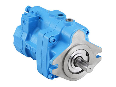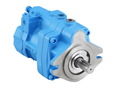
PVS-1B-16N0-E13
Description: Variable Volume Piston Pump
The PVS Piston Pump is a NACHI proprietary energy saving, low noise pump with a semi-circular barrel swash plate that receives pressure on its surface and ensures a stable discharge volume by eliminating excess discharge. The swash plate conserves energy, enables the effective use of power corresponding to the load cycle, and helps reduce hydraulic costs. Proprietary low noise mechanics are incorporated on the shoe, swash plate, valve plate, and other locations to ensure a quieter operation.
Features:
| Spec | Value |
|---|---|
| Series | PVS: Variable Piston Pump |
| Size | 1 |
| Mount | B: Flange Type |
| Capacity | 16 (cm³/rev) |
| Control Mechanism | N: Pressure Compensation Type |
| Pressure Adjustment Range | 0: 286 - 500 psi |
| Aux Symbol | N/A |
| Design | E13: SAE Piping |
| Weight (lb/kg) | 23.2 / 10.5 |
Values provided may differ based on other specifications. Please consult the product documentation for values specific to the model number.
*Please consult product documentation for specific values
Additional Documents:
Looking for distributors outside of the US? Find Mexican Distributors or Canadian Distributors
Notes:
- Design No. 30 is applied on PVS-0B to make the pump more compact, lighter, and reduce noise.
- Production of PVS-3B has been discontinued. Use PZS-3B
- Pressure adjustment 3 type has been added to the PVS-1B-22 and PVS-2B-45. (Design No. 20 is applied only on PVS-2B-45*3)
Handling:
- Use flexible couplings for connecting the pump shaft to the drive shaft, and prevent a radial or thrust load from being applied on the pump shaft.
- For centering of the pump shaft, limit the eccentricity between the drive shaft and hydraulic pump shaft to 0.05 mm, and keep the angle error within 1 inch.
- Set the length of insertion between coupling and hydraulic pump shafts so that it is within at least 2/3 or more of the coupling width.
- Use a sufficiently rigid pump mounting base.
- Set the pressure on the pump suction side to -4 psi (-0.03 MPa) or more (suction port flow velocity within +6 ft/sec or 2 m/sec).
- Raise part of the drain piping to above the top most part of the pump body and insert the return section of the drain piping into the hydraulic fluid. Also, observe the values in Table 1 to limit the drain back pressure to 14.5 lbs/in² (0.1 MPa).
- Mount the pump so the pump shaft is oriented horizontally.
Similar Items (415)

Variable Volume Piston Pump
PVS-1A-16N0-12
Variable Volume Piston Pump
PVS-1A-16N1-12
Variable Volume Piston Pump
PVS-1A-16N2-12
Variable Volume Piston Pump
PVS-1A-16N3-12
Variable Volume Piston Pump
PVS-1B-16N0-12
Variable Volume Piston Pump
PVS-1B-16N1-12
Variable Volume Piston Pump
PVS-1B-16N2-12
Variable Volume Piston Pump
PVS-1B-16N3-12
Variable Volume Piston Pump
PVS-1A-16N0-E13
Variable Volume Piston Pump
PVS-1A-16N1-E13
Variable Volume Piston Pump
PVS-1A-16N2-E13
Variable Volume Piston Pump
PVS-1A-16N3-E13
Variable Volume Piston Pump
PVS-1B-16N1-E13
Variable Volume Piston Pump
PVS-1B-16N2-E13
Variable Volume Piston Pump
PVS-1B-16N3-E13
Variable Volume Piston Pump
PVS-1A-16N0-Z-12
Variable Volume Piston Pump
PVS-1A-16N1-Z-12
Variable Volume Piston Pump
PVS-1A-16N2-Z-12
